
UML state machine diagram
Unified Modeling Language (UML) is a powerful tool used in software engineering to visualize, design, and communicate the structure and behavior of systems. Among its various diagram types, the UML State Machine Diagram stands out as a fundamental representation of the dynamic behavior of an object or system. In this article, we will delve into the intricacies of UML State Machine Diagrams, exploring their components, symbols, applications, and benefits.
Introduction to UML State Machine Diagrams
At their core, UML State Machine Diagrams capture the state transitions and behaviors of objects or entities within a system. These diagrams provide a clear representation of how an object's state changes in response to events and conditions, ultimately leading to a better understanding of the system's behavior. UML State Machine Diagrams are particularly useful in modeling complex behaviors, especially those that involve multiple states and intricate transitions.
Components of UML State Machine Diagrams
-
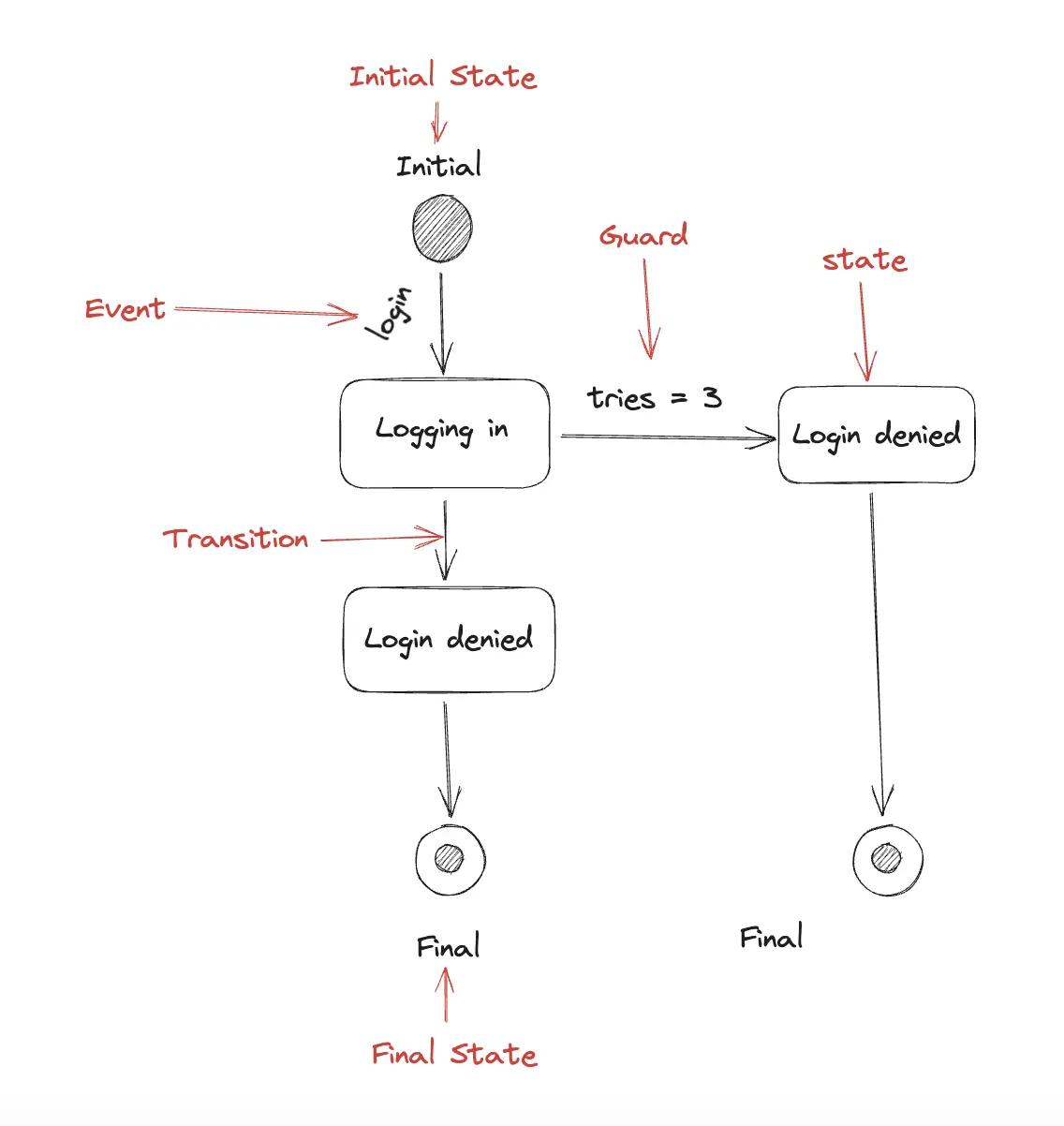
States: A state represents a condition or mode that an object can be in. For example, in a traffic light system, states could include "Red," "Yellow," and "Green." Each state is depicted as a rounded rectangle with the state's name inside.
-
Transitions: Transitions depict the change from one state to another due to events or conditions. These are represented by arrows connecting the states and are labeled with the triggering event or condition that leads to the transition. Transitions can also have associated actions or effects that occur when the transition takes place.
-
Events: Events are occurrences that trigger transitions between states. These can be external events like user inputs or internal events like timers reaching a certain value.
-
Actions: Actions are behaviors or activities that are executed when a transition occurs. They can be associated with transitions to specify what happens during the transition, aiding in understanding the system's behavior.
-
Guards: Guards are conditions that must be satisfied for a transition to occur. They are often depicted as expressions associated with transitions, ensuring that the appropriate conditions are met before a state transition happens.
-
Initial and Final States: An initial state indicates the starting point of the state machine, while a final state marks the end point. An object may enter the final state after reaching a specific state or completing its task.
Symbols in UML State Machine Diagrams
- State: Rounded rectangle with the state's name inside.
- Transition: Arrow connecting states, labeled with the triggering event/condition.
- Event: Named occurrence that triggers transitions.
- Action: Activity that occurs during a transition.
- Guard: Condition that must be fulfilled for a transition to happen.
- Initial State: Filled circle indicating the initial state.
- Final State: Bullseye-like symbol representing the final state.
Applications of UML State Machine Diagrams
UML State Machine Diagrams find applications across various domains:
-
Software Development: In software engineering, these diagrams model the behavior of objects or components within a system. They assist developers in understanding and implementing complex state transitions and behaviors.
-
Embedded Systems: For systems like IoT devices or hardware controllers, state machine diagrams help designers visualize how the system responds to different inputs and events.
-
Game Development: Games often involve complex character behaviors and interactions. State machine diagrams aid in designing the characters' states, animations, and responses to player actions.
-
Business Processes: State machine diagrams can represent the lifecycle of a business process or workflow, helping to identify bottlenecks and areas of improvement.
-
Communication Protocols: When designing communication protocols or network systems, state machine diagrams are invaluable for illustrating how devices or systems react to various messages and conditions.
Benefits of Using UML State Machine Diagrams
-
Clarity and Understanding: These diagrams provide a visual representation of dynamic behavior, making it easier for stakeholders to understand how a system operates.
-
Complexity Management: UML State Machine Diagrams help manage complex behaviors by breaking them down into states, transitions, and actions, simplifying the design process.
-
Requirements Validation: By mapping states and transitions to requirements, developers can ensure that the system fulfills the intended behaviors and functionalities.
-
Effective Communication: UML State Machine Diagrams serve as a common language between developers, designers, testers, and clients, facilitating effective communication and collaboration.
-
Documentation: These diagrams serve as comprehensive documentation for the system's behavior, aiding in future maintenance and updates.
Conclusion
UML State Machine Diagrams are a powerful tool for modeling and understanding the dynamic behavior of systems, objects, and entities. By visually representing states, transitions, events, and actions, these diagrams offer a clear picture of how a system behaves under different conditions. Their applications in software development, embedded systems, game design, and more make them a crucial asset for designers, developers, and stakeholders alike. With their ability to simplify complexity and improve communication, UML State Machine Diagrams continue to play a pivotal role in modern software engineering and system design.
